Location: Institute of Chemistry, Albert-Einstein-Str.3a, ground floor, left hand side/ R 048
The fuel laboratory of the Department of Piston Engines and Internal Combustion Engines is a specialised laboratory with measuring stations for the standardised determination of fuel and lubricant parameters as well as for the standardised determination of environmental pollutants in various environmental matrices within the framework of teaching and research.
The task of the research laboratory is to carry out investigations into the effectiveness of newly developed fuel and lubricant additives, the testing and quality assurance of new test fuels and to contribute to their standardisation. Another focus of our work is the development, adaptation or new development of suitable analysis methods for characterising and monitoring the system solutions developed at our institute on technical machines and systems. The laboratory also has many years of experience in investigating the causes of internal and external cases of damage, as well as an extensive arsenal of sophisticated and complex analysis methods that go far beyond the scope of a routine laboratory. Over the last 5 years in particular, the laboratory has developed into a recognised centre of excellence for the analysis of biogenic fuels.

Tuition
In the lectures on fuels and lubricants, students in the 6th and 8th semesters of mechanical engineering (major), computer science and economics (technical elective subject II) are familiarised with the latest chemical and chemical-physical analysis methods in laboratory practice in combination with combustion engines and chemical fundamentals of environmental technology,. The high-performance analytical measuring stations are also available to students and doctoral students for their dissertations and theses.
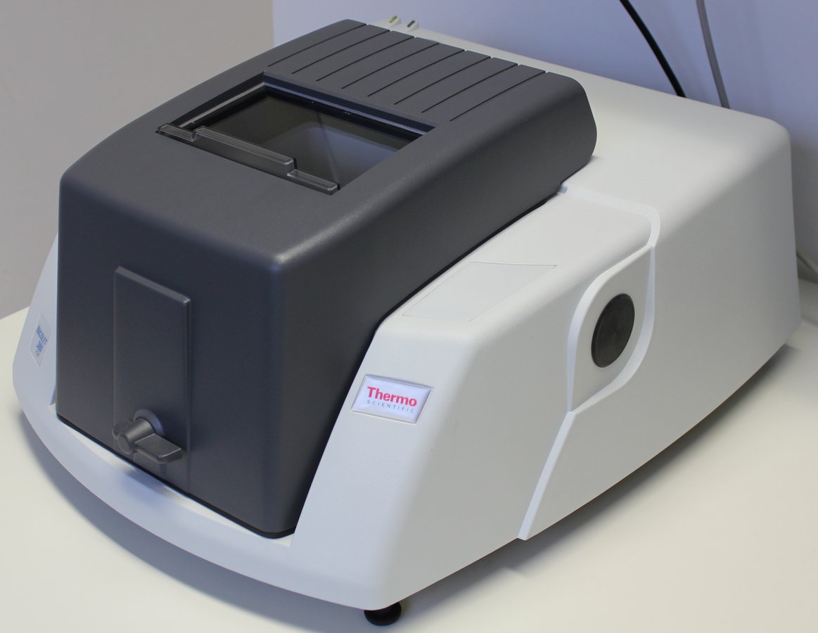
3D-Laser Scanning Microscope

With the support of the European Regional Development Fund (ERDF), a new laser scanning microscope was put into operation at the Department of Piston Engines and Internal Combustion Engines on 28 August 2015.
The 3D laser scanning microscope is a light microscope in which a focussed laser beam scans a specimen. This enables it to carry out non-contact profile, roughness and layer thickness measurements in the micrometre range on almost any material.
The strengths of the measuring system are
- Precise measurements thanks to laser scanning
- 3D measurements in colour
- Roughness measurements in the nanometre range
- Deep-focus colour images
This device system has a violet laser (λ = 408 nm, laser class II) and enables measurements with a height resolution in the z-direction of up to 0.5 nm.
Keyence VK-X200
- Optical system: Confocal pinhole aperture
- Total magnification: up to 28,800 x (full image on 23 inch monitor)
- Detectable image field: 11 - 5400 µm
- Laser measurement speed: 4- 7900 Hz
Cold-Filter-Plugging-Point (CFPP)
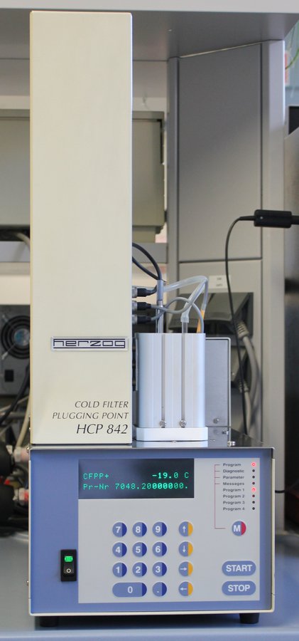
The cold filter plugging point (CFPP) - the filterability limit according to EN 116 - is a quality feature of fossil diesel fuel (DF) and biodiesel. The CFPP point is the temperature at which the DK sucked through blocks a standardised filter. The determination of the CFPP value of diesel fuel, i.e. the assessment of its suitability for winter use in accordance with EN 590 - Climatic requirements and test methods - National part of the standard - Classification according to climatic classes, is part of the practical course ‘Fuels and lubricants’.
Pour Point/Plugging Point/Cloud Point
The students characterise the winter suitability of marine fuels in accordance with ISO 8217 by means of a pour point and cloud point determination. The cloud point (according to DIN ISO 3015) is the designation for the temperature point at which the turbidity of mineral oils begins as a result of the precipitation of paraffin or other ingredients. Testing the pour point, the temperature at which an oil is no longer caused to flow by its own weight when continuously cooled by 3K in a prescribed test glass, plays an important role in assessing the low-temperature behaviour of lubricants under storage, transport and operating conditions. The pour point of mineral oils is calculated from the pour point by adding 3K to the read pour point temperature. The pour point has replaced the pour point as a quality criterion for DK and heating oils. The above-mentioned parameters of mineral and bio-oils are constantly used in research projects, particularly in the field of biogenic fuels, to assess the cold behaviour or to check the improvement of cold resistance through additives.
Coking tendency/ash content
The coke residue of DK and vegetable oil methyl ester is determined by carbonising the last 10% of the distillation residue. For vegetable oil, residual oils and lubricating oils, the coke residue is determined on the total sample. This simulates the combustion of fuel on a surface without oxygen. The coke residue consists of organic and inorganic components and is a measure of the coking tendency of the fuel at the injection nozzles and residue formation in the combustion chamber. The ash content (oxide ash) describes the proportion of inorganic solids in the fuel. High ash contents can be caused, for example, by the ingress of dust. Increasing ash content increases the risk of abrasion (wear) occurring in the injection pump, in the injection nozzles and in the combustion chamber. The ash content is determined by igniting and burning off a sample until ash and carbon remain. The residue is incinerated in a special furnace, cooled and balanced. Both parameters can be determined in the MCR tester in different test cycles. The measuring station is used in the ‘Fuels and Lubricants’ practical course to determine the ash and MCCR (Micro Conradson Carbon Residue) of DK and a marine fuel as well as in heavy fuel oil, pyrolysis oil and bio-oil research for the classification and quality control of fuels and lubricants.
Automatic density determination
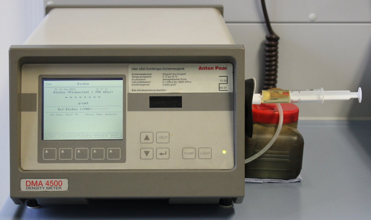
The density measurement at this measuring station is carried out with the DMA 4500 (Anton Paar) using the oscillating U-tube method. Approximately 1ml of sample is filled into a vibrating tube. The change in the oscillation frequency and thus the oscillation period due to the resulting change in the oscillating mass of the tube is used to determine the density of the sample using calibration data. The device provides highly accurate measurement results over a very wide viscosity and temperature measuring range in accordance with DIN EN ISO 12185, with automatic temperature compensation and conversion to concentration, relative density or other density-related values if required. Nine different preset measuring methods enable, for example, the measurement of density with viscosity correction of samples of the product group crude oil, fuels to heating oil, lubricating oils at any temperature, whereby the output of the API density, API number and relative density after temperature compensation and conversion to 15°C (standard temperature) is displayed as the result. Density is a physical parameter that is used in teaching and research to characterise and identify crude oils, fuels and lubricants. Density can be used to detect impurities or mixtures with other fuels.The density can be used to detect impurities or mixtures with other fuels. Density is an important parameter for handling and trading fuels and lubricants (mass/volume conversion), for deriving fuel properties in the form of statistical laws (e.g. lower calorific value, ignitability) and for converting dynamic viscosity into kinematic viscosity. It is also important for fuel preparation in centrifugal separators and for calculating the flow rate through nozzles. Density measurement using the oscillating U-tube method is demonstrated in the lecture ‘Fuels and lubricants’. Density measurement using this method is part of the petrol and diesel fuel standard (EN 228 and EN 590), the biodiesel standard EN 14214, ISO 8217 (requirements for marine fuels) and DIN V 51605 for rapeseed oil fuel.
Falling ball viscometer
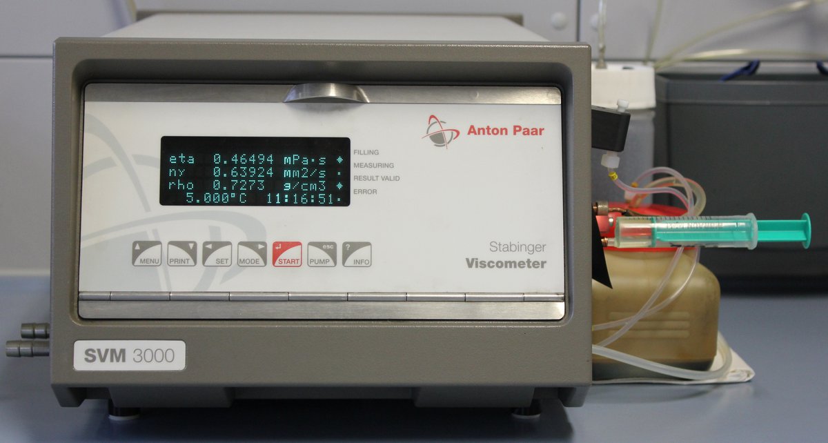
The density measurement at this measuring station is carried out with the DMA 4500 (Anton Paar) using the oscillating U-tube method. Approximately 1ml of sample is filled into a vibrating tube. The change in the oscillation frequency and thus the oscillation period due to the resulting change in the oscillating mass of the tube is used to determine the density of the sample using calibration data. The device provides highly accurate measurement results over a very wide viscosity and temperature measuring range in accordance with DIN EN ISO 12185, with automatic temperature compensation and conversion to concentration, relative density or other density-related values if required. Nine different preset measuring methods enable, for example, the measurement of density with viscosity correction of samples of the product group crude oil, fuels to heating oil, lubricating oils at any temperature, whereby the output of the API density, API number and relative density after temperature compensation and conversion to 15°C (standard temperature) is displayed as the result. Density is a physical parameter that is used in teaching and research to characterise and identify crude oils, fuels and lubricants. Density can be used to detect impurities or mixtures with other fuels. Density is an important parameter for the handling and trading of fuels and lubricants (mass/volume conversion), for deriving fuel properties in the form of statistical laws (e.g. lower calorific value, ignitability) and for converting dynamic viscosity into kinematic viscosity. It is also important for fuel preparation in centrifugal separators and for calculating the flow rate through nozzles. Density measurement using the oscillating U-tube method is demonstrated in the lecture ‘Fuels and lubricants’. Density measurement using this method is part of the petrol and diesel fuel standard (EN 228 and EN 590), the biodiesel standard EN 14214, ISO 8217 (requirements for marine fuels) and DIN V 51605 for rapeseed oil fuel.
Total contamination Biodiesel/rapeseed oil fuel/Diesel fuel
The total contamination is the mass fraction of undissolved foreign substances (particles) in the fuel. The determination is carried out by filtering the sample through a membrane with an average pore size of 0.8 µm. The residue is washed with solvent, then dried and weighed. High levels of foreign matter lead to filter blockage, clogging of injection nozzles, abrasion on the injection pump and nozzles as well as deposits in the combustion chamber. Viscosity measurement using this method is part of the petrol and diesel fuel standard (EN 228 and EN 590), the biodiesel standard EN 14214, ISO 8217 (requirements for marine fuels) and DIN V 51605 for rapeseed oil fuel.
Boiling analysis (automatic distillation machine)
Automatic distillation at atmospheric pressure is used to determine the boiling curve of a fuel. The distillation curve (the volatility/evaporation tendency) of hydrocarbons is of great importance with regard to the safety and usability of fuels. The distillation range provides important information about the composition and behaviour during storage and use. Limit values for the distillation curve are specified in most requirements for mineral oil-based distillates (see e.g. EN 590 Requirements for diesel fuel). The boiling curve of a fuel provides information, for example, on the cold start behaviour, the duration of the heating period, the risk of lubricating oil dilution, the risk of carburettor icing and the risk of vapour bubble formation. The distillation of a diesel fuel and its assessment in accordance with EN 590 is part of a student experiment in the practical course ‘Fuels and Lubricants’. Distillation is of great importance in research in the field of biogenic fuels, as these fuels differ fundamentally from mineral diesel in terms of their boiling point. The boiling point curve is therefore the basis for optimising the combustion process in series diesel engines or converted engines.
Gas chromatography
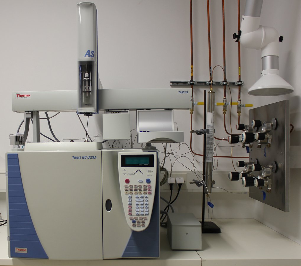
Gas chromatography (GC) is a method for separating substances, for separating mixtures of substances that are present in gaseous form or can be vaporised without decomposition, whereby a gas serves as the mobile phase. A GC analysis begins with the application of a gas, a vaporisable liquid or a vaporisable solid to the thermostated separation column. With the help of the carrier gas (He, N2 or H2), the substances are transported through the column, where chromatographic separation takes place due to different interactions between the sample substances and the separation phase on the column. The separated substances reach the end of the column one after the other and are displayed as peaks by a detector with the aid of the evaluation unit. The qualitative evaluation is carried out via the retention time (time from injection to the substance maximum). Quantitative evaluation is carried out by determining the area of the substance peaks. A flame ionisation detector is used as the detector. The gas chromatography method is the subject of an experiment in the practical course ‘Chemical Principles of Environmental Technology’. When analysing waste water from a paint spraying plant for BTX aromatics, the students carry out both a qualitative and quantitative determination of the BTX aromatics (benzene, toluene and o-, m- and p-xylene) contained in the waste water.When analysing wastewater from a paint spraying plant for BTX aromatics, the students carry out both a qualitative and quantitative determination of the BTX aromatics (benzene, toluene and o-, m- and p-xylene) contained in the wastewater. In research in the field of biogenic fuels, GC is used to determine glycerol, mono, di and triglycerides in biodiesel in accordance with DIN V 51606 and DIN EN 14214 and to analyse the components of biogas (thermal conductivity detector). Furthermore, the boiling behaviour of fuels can be assessed using simulated distillation.
HFRR
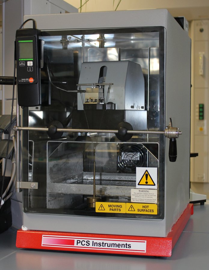
The HFRR method (high-frequency reciprocating rig) is a laboratory test rig for determining the lubricity of diesel fuel using a vibration wear tester. All components of the diesel injection equipment whose tribological contacts are surrounded by DK require a sufficient lubricating effect of the DK. Wear, which manifests itself in the form of high wear rates or scuffing, leads to a reduction in the service life of the diesel injection equipment. If this wear behaviour can be traced back to the tribological properties of DK, this is referred to as insufficient lubricity. There is a correlation between wear parameters from the tribological laboratory tests and the evaluation of function-critical components of the injection equipment. The lubricity of the fuel can be derived with sufficient certainty on the basis of the wear parameters from the laboratory test. This involves measuring the wear calotte on a ball that has been moved back and forth in a liquid bath (fuel) on a stationary disc for 75 minutes under constant contact pressure. According to the latest developments, the HFRR method will also become increasingly important in the assessment of petrol fuels in the future. The HFRR abrasion test is carried out as a practical test in the ‘Fuels and Lubricants’ practical course at petrol stations and its lubricity is tested for conformity with standards. The HFRR value is a component of the diesel fuel standard EN 590 and a central topic of research projects in the field of modern low-sulphur and sulphur-free fuels, as the lubricity of fuels decreases as the content of sulphur compounds decreases. The lubricity can be improved by adding small quantities of biofuels to low-sulphur diesel.
HPLC
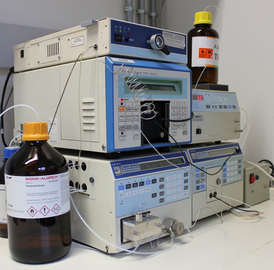
High Performance or High Pressure Liquid Chromatography is a method of column chromatography that requires the use of high pressures (up to 400 bar) due to the fineness of the separating materials. The HPLC apparatus consists of two gradient pumps with eluent reservoirs, the sample feed system, the separation column, the detectors and the data recording system. In the simplest case, elution can be carried out isocratically with a solvent or a constant solvent mixture. Difficult separation problems, on the other hand, require gradient elution. The system is controlled by a PC, which also analyses the chromatograms. Important parameters for the qualitative evaluation are the dead time (to), the net retention time (tR) and the resulting total retention time (tg), which is linked to the corresponding retention volumes via the volume speed. The quantitative evaluation is carried out via the peak areas. The UV detector is predominantly used as a detector due to its ease of use. Depending on the problem, other detectors such as refractive index, fluorescence or conductivity detectors are also used. In the practical course ‘Chemical Principles of Environmental Technology’, HPLC is the subject of a PAH determination in a student experiment.Analytical HPLC plays a role in the determination of the aromatic content (mononuclear, binuclear and polynuclear aromatics) in DK (EN 590). This method is used in research (environmental process engineering) for the quantitative determination of non-ionic surfactants in waste water and for separating the surfactants into the individual homologues and isomers.
Ion chromatography
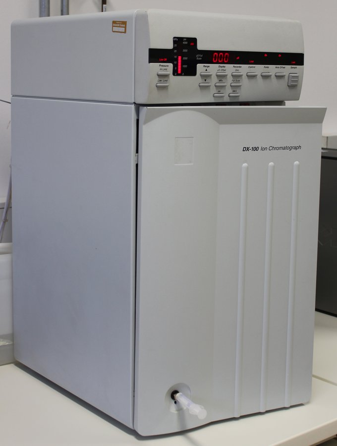
Ion chromatography (IC) is a special form of high-pressure liquid chromatography (see HPLC measuring station) and is a versatile analytical technique for determining ionic species using a conductivity detector. The main area of application in the operating materials laboratory is the determination of inorganic anions (chloride, sulphate, phosphate, nitrate). Following mineralisation (complete combustion in the calorimetric bomb, see calorimeter measuring station), the sulphur or Cl content of fuels and combustibles can be determined after absorption of the resulting SO2 or HCl in an aqueous buffer solution. The chloride content of wastewater also plays a major role in environmental process engineering when selecting the treatment process (risk of new AOX formation) and carrying out analyses (chloride interferes with COD determination, for example). In the practical course ‘Chemical Principles of Environmental Technology’, IC is the subject of the student experiment ‘Determination of chloride in drinking water’.
FT infrared spectroscopy
Infrared spectroscopy is a method of optical spectroscopy in which the absorption spectra of organic solid, liquid or gaseous compounds in the near (NIR), mid (MIR) and far (FIR) infrared range are used for qualitative or quantitative analysis and for determining composition. IR spectra are vibration spectra that arise when the atoms involved in the bonds within the molecules vibrate. The IR rays from the light source pass through the cuvette, where the molecules of the substance absorb rays of a certain wavelength in certain percentages, resulting in an absorption spectrum. This absorption spectrum is more or less characteristic of each individual organic compound. The IR radiation absorption registered by the receiver is converted into a signal voltage of 10–7 to 10–9V, amplified 106 to 109 timesand converted so that the respective IR transmittance of the substance is displayed in an electronic recording device as a curve (IR spectrum) depending on the wavelength. The abscissae represent the wavelengths (or their reciprocals, the wave numbers v) – qualitative statement, while the corresponding ordinates indicate the transmission – quantitative statement. The IR device works according to the Fourier transform technique (FT-IR or Fourier spectroscopy) and can record the entire spectrum of the sample in less than 1 second. FT-IR spectrometers contain interferometers instead of a dispersing agent. The IR method is part of a practical experiment in the course ‘Chemical Fundamentals of Environmental Technology’, in which a coalescence system is evaluated by analysing oil-containing wastewater before and after treatment. In the student experiment, the total hydrocarbon content in the wastewater is determined before and after treatment and the effectiveness of the coalescence separator is evaluated with regard to the legal limits for oil in wastewater. In research, the device is used to determine bio-oils in lubricants, to identify lubricating oils (mineral/synthetic), to identify contaminants (water, glycol) in lubricating oils, to determine soot in used oils and, in general, to elucidate the structure of unknown substances.
Calorimeter
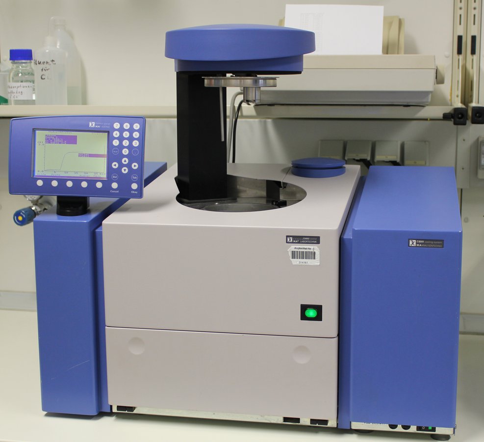
A liquid calorimeter system from IKA is used to determine the amount of heat released during combustion processes, i.e. to determine the calorific value or heating value. The calorimeter consists of a sealed, thick-walled steel vessel (calorimetric bomb) in which a precisely weighed quantity of a solid or liquid substance is burned in oxygen at a pressure of 30–35 bar after ignition by an electric glow wire. During combustion, the bomb is immersed in a measured quantity of water; the heat of combustion of the fuel is transferred to the water, causing a measurable increase in temperature, from which the amount of heat released can be determined. The heat capacity of the calorimeter system must be determined under identical conditions using a reference substance (e.g. benzoic acid). The calorific value (Ho) is defined as the quotient of the amount of heat released during the complete combustion of a specific amount of fuel and the mass of this fuel. The symbol Ho is derived from the former designation ‘upper heating value’ = combustion heat. In terms of size, the heating value is smaller than the calorific value; it can be calculated from the latter – in accordance with DIN 51900 Parts 1–3 (Aug. 1977) – with the aid of the evaporation enthalpy of water. The calculation is performed, for example, according to Hu=Ho–r·Wwater, where r = specific evaporation heat of water at 25°C (= 2.442 kJ/g) and Wwater is the quotient of the masses of H2O formed during the fuel element analysis and the fuel used (weighed) for this purpose. The calorimetric measurement method is not only useful in research (heavy oil research, pyrolysis oil research) for the technical testing of fuels (heating oils, coal) and determining their quality, but also proves indispensable for determining thermodynamic data of substances and reactions (thermodynamics). The determination of the lower heating value of DK and heavy fuel oil is the subject of a student experiment as part of the ‘Fuels and Lubricants’ practical course.
pH-Value
The pH value is a measure defined in DIN 19260 as the decimal logarithm of the hydrogen ion activity multiplied by (–1). The pH value of an aqueous solution is determined by potentiometric measurement using an H+ ion-sensitive electrode (glass electrode). A single-electrode measuring cell (glass electrode with integrated reference electrode) is used. This gives a change of 59.1 mV per pH level at 25°C. The glass electrode provides reliable, reproducible results in the range 2<pH<12. The pH value plays an extremely important role in environmental chemistry and technology. It influences numerous chemical processes, in particular chemical equilibrium reactions of all kinds. For this reason, pH measurement is of greater practical importance for industry and agriculture, for example, than the determination of the concentration of any other ions. The precise determination and maintenance of specific pH values – with the aid of data processing, control and regulation (automation) – is important in a wide range of technical processes, such as the neutralisation of waste water, chlorination of swimming pools and the treatment of industrial water (precipitation, flocculation, complex formation). pH measurement is a routine method that is important in every analytical laboratory. The results of many analytical methods are influenced by the pH of the solvent or buffer, e.g. ion exchange chromatography or titration analysis. The pH value is important in determining lime aggressiveness and acid and base capacity. pH value determinations are the subject of a practical experiment in the ‘Chemical Fundamentals of Environmental Technology’ course: separation of a surfactant-stabilised oil-in-water emulsion by flocculation with iron sulphate. Here, students determine the pH value of the wastewater before and after chemical treatment. Furthermore, the acid capacity of the wastewater is determined and the optimum pH value for flocculation is set.
Optical emission spectroscopy (ICP-OES)
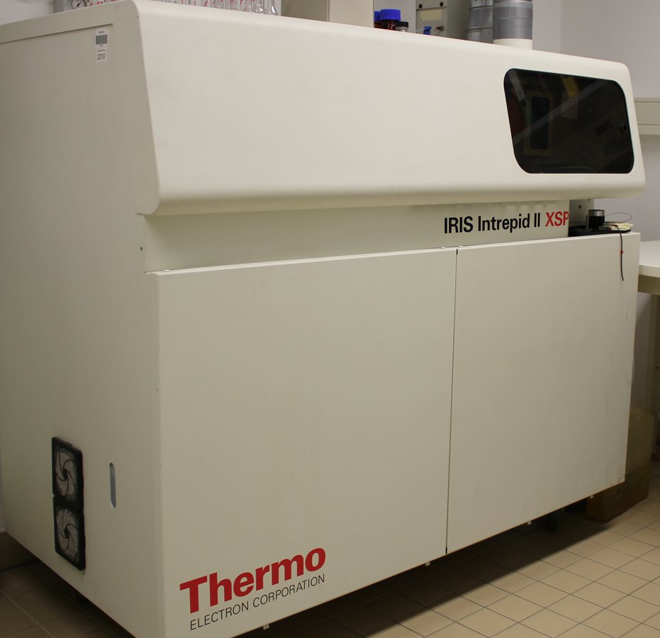
Optical emission spectroscopy (OES) is a method of spectroscopy in which atoms are excited to emit radiation that is characteristic of them. The excitation is carried out by means of ICP (inductively coupled plasma). In OES, line spectra are observed. The method is particularly useful for multi-element analysis. ICP-AES is used in research to determine additive elements and wear metals, as well as to determine phosphorus and sulphur in fuels and combustion residues. In environmental technology/environmental chemistry, it is used to determine heavy metals in a wide variety of sample matrices (water, soil, sludge, ash). The ICP-AES method is demonstrated to students in the ‘Fuels and Lubricants’ lecture. The determination of heavy metals in contaminated soil using ICP-AES is the subject of a student experiment in the ‘Chemical Fundamentals of Environmental Technology’ practical course.
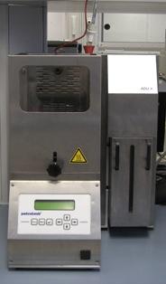
Spoilage detection
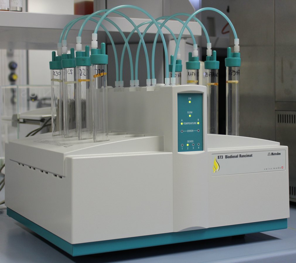
The spoilage of vegetable and animal fats, which can be detected in its early stages by a reduction in smell and taste (rancidity), is largely due to chemical changes caused by exposure to atmospheric oxygen. These oxidation processes, which occur slowly at ambient temperature, are referred to as autoxidation. They start with radical reactions on unsaturated fatty acids and lead to a wide variety of degradation products in a multi-stage process, in particular peroxides, aldehydes, alcohols and carboxylic acids. In the Rancimat method, the vegetable oil fuel sample (fatty acid methyl ester (biodiesel) or vegetable oil) is exposed to a stream of air at temperatures of 110°C. The volatile degradation products are transferred with the air stream into the measuring vessel, where they are absorbed by the measuring solution (distilled water). Continuous recording of the conductivity of this measuring solution produces oxidation curves, whose inflection point is referred to as the induction time and is a good parameter for the oxidation stability of vegetable oil fuels. Oxidation stability describes the ageing state and storage stability of biodiesel and vegetable oil, which is why this parameter is of central importance in all research projects in the field of biogenic fuels. The oxidation stability parameter determined by this method is part of the fuel standard for biodiesel EN 14214 and DIN 51605 for rapeseed oil fuel.
Flash point
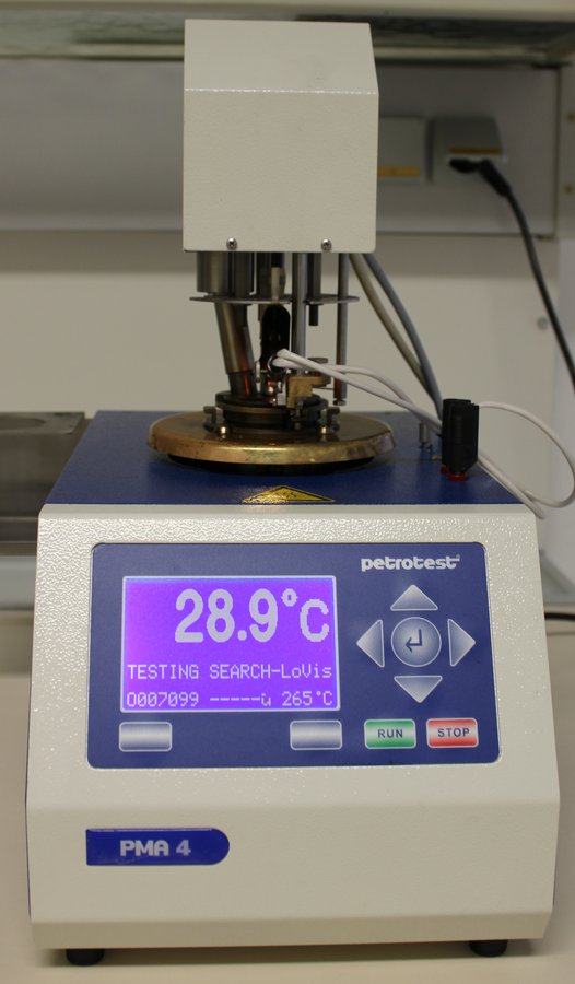
The flash point according to DIN EN ISO 2719 is the measured temperature at which vapours develop in a closed container that lead to a vapour-air mixture that can be ignited by an external source. The flash point is particularly important when classifying liquids into hazard classes in accordance with the Industrial Safety Regulation. Safety precautions for storage and transport must be taken in accordance with the hazard class. Even slight mixing of different fuels, e.g. during transport, can cause significant deviations from their characteristic flash point. On board ships, for example, only fuels with a flash point above 60°C may be used. Due to their high flash point (> 100°C), vegetable oil fuels are not classified as hazardous substances under the Industrial Safety Regulation. Under German law, many exemptions from safety regulations are permitted for the storage and transport of these fuels. Additives, mixing with other fuels or poor quality can cause the flash point to fall well below 100°C, which can lead to hazardous situations. The above information is taught to students in the ‘Fuels and Lubricants’ course. Determining the flash point of fuels and assigning them to the appropriate hazard classes is part of the practical training. Flash point determination is used in research projects in the field of biogenic fuels and marine fuels for quality control purposes.
Titration system
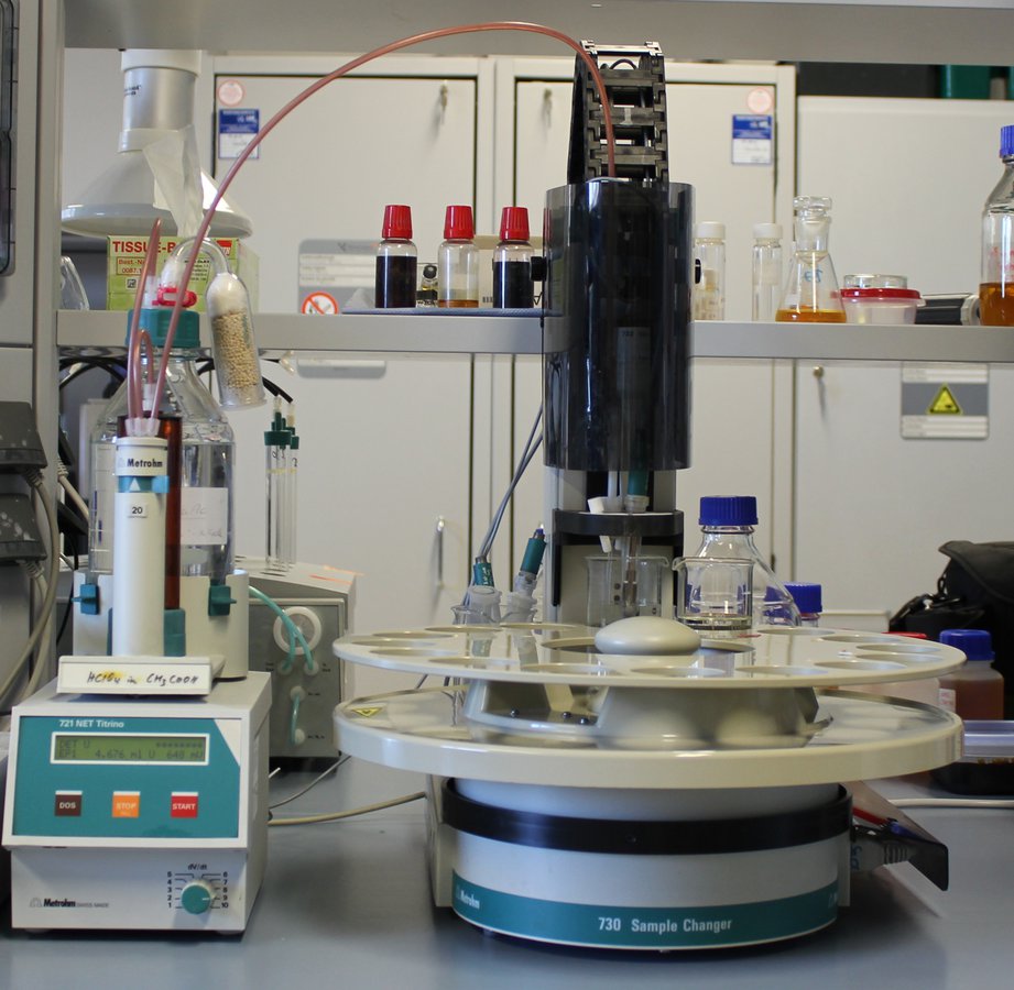
The PC-controlled titration system (Metrohm) is used to perform potentiometric titrations. The system consists of two titration stands, an automatic sample changer, a coulometer and an analytical balance. The initial weight of the starting material is automatically recorded via the connected analytical balance and stored directly in the database together with the sample number, the date of the determination, the analysis method and the titration result. The special control and evaluation software allows different analysis methods to be carried out in parallel and the titration parameters to be specifically adapted to the analysis task. The performance of acid-base titrations with potentiometric endpoint indication in aqueous and non-aqueous systems (oil phase) is taught in the subject ‘Power and Lubricants’ as an important part of power and lubricant analysis. This includes the determination of the following characteristic values:
- Total base number (TBN) in lubricating oils according to DIN ISO 3771 (determination of the alkaline reserve in oil for neutralising acidic combustion products and contaminants)
- Saponification number according to DIN 51559-1 (determination of saponifiable components in oil, additives, entry of rapeseed oil fuel into the lubricating oil
- Iodine number according to DIN EN 14111 in biofuels (number of double bonds, allows conclusions to be drawn about oxidation stability/thermal stability, storage stability)
- Water content according to Karl Fischer according to DIN 51777 in lubricants and marine fuels (quality parameter, indication of damage, reduced lubricity, for water contents in the percentage range)
- Coulometric water determination in rapeseed oil fuels according to DIN EN ISO 12937 (quality parameter, sensitive method for water content in the ppm range)
- Neutralisation number according to DIN 51588. DIN EN 14104 (proportion of acidic products in lubricating oil or fuel, indication of corrosion risk and incipient oil ageing)
Rheometer
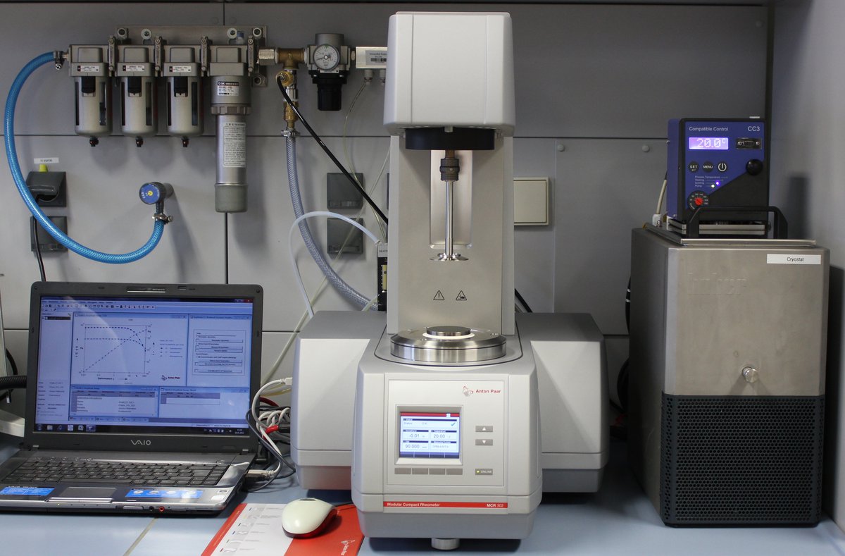
Rheological investigations deal with the flow and deformation behaviour of substances. These properties are determined by the shape and arrangement of the molecules, their concentration, the temperature and the cross-linking. The rheometer can be used to perform a wide range of different measurements that provide information about the flow behaviour and shear behaviour of the sample and its internal structure.
For example, viscosities can be recorded as a function of the shear rate at different temperatures. Furthermore, the amplitude test provides information about the limits of the linear-viscoelastic range (range in which deformation does not yet cause any change in the substance structure), the yield point (start of change in the substance structure) and the flow limit (transition from the gel to the liquid state and vice versa). The frequency test provides information about the short- and long-term behaviour of the samples, and the structure build-up test allows the behaviour of the sample to be observed after a specified load.
The laboratory has an MCR 302 rheometer from Anton Paar with a Peltier system that allows fast and accurate temperature control between -40°C and 200°C.
Three different measuring systems are available for the measurements.
- CP50-0.5/TG (cone)
- PP50/TG (plate)
- PP25/TG (plate)
Ball-on-disc tribometer with pressure chamber (High Pressure Reciprocating rig - HPR)
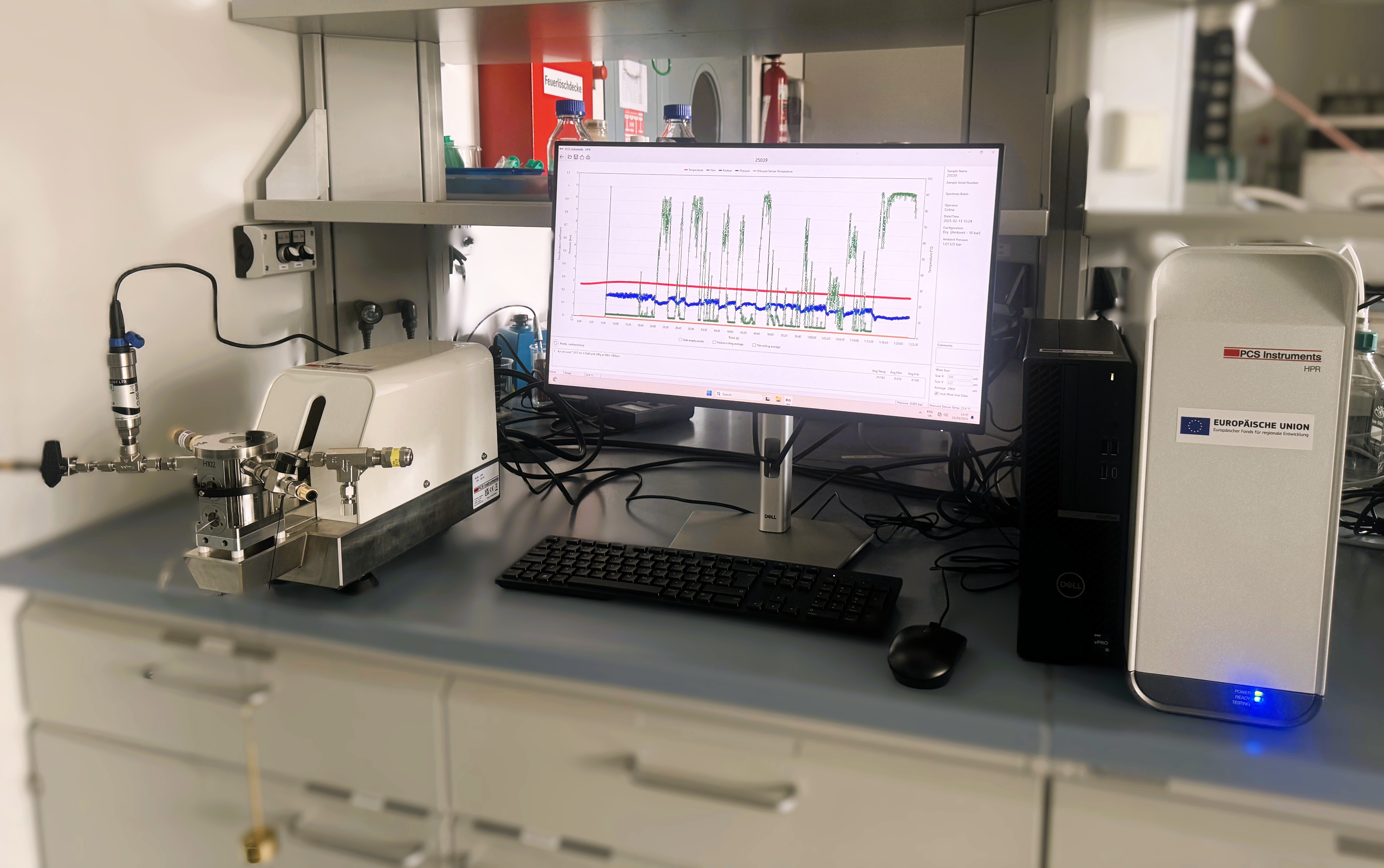
Hydrogen-based fuels such as methanol or gaseous fuels such as hydrogen and ammonia for combustion engines have been the subject of current research for several years, particularly in the field of maritime shipping. Particularly when used in engines with fuel-lubricated injection components, the problem is that the above-mentioned fuels have very poor lubricity and must be tested accordingly to prevent increased component wear. The HFRR test (High Frequency Reciprocating Rig Test) was developed to evaluate the lubricity of liquid fuels. This test simulates sliding wear in the injection pump by oscillating a 6 mm steel ball back and forth on a polished steel plate with the previously determined parameters of frequency, duration, travel and load. The test specimens are immersed in the temperature-controlled fuel. The wear scar diameter (WSD) is measured as the average wear diameter after 75 minutes. In addition, the lubricating film thickness and the coefficient of friction are recorded in a diagram. For highly volatile fuels such as methanol or gaseous fuels such as hydrogen and ammonia, a friction and wear testing system (plate-ball tribometer) with a completely sealed pressure chamber that can be operated under high pressure is required. The removable chamber design maintains the pressure outside the system so that test mixtures can be prepared on site. The HPR system is a fast, reliable and cost-effective way to test volatile or gaseous fuels using commercially available, inexpensive and variable test specimens and small test volumes.
Typical planned applications are:
- Lubricity tests on volatile e-fuels and their blends (e.g. methanol, methanol blends)
- Tests on gaseous e-fuels (dimethyl ether, ammonia and hydrogen) under controlled atmosphere
- Determination and efficiency testing of suitable additives (lubricity improvers) and their optimal dosage
- Behaviour of highly volatile lubricants under low pressures (direct friction and wear measurements under defined test conditions)
- Behaviour of lubricating oils with functional water content, verification of superlubricity
- Lubricity studies under controlled atmosphere, e.g. hydrogen or ammonia atmosphere
- Investigation of the surface morphology of component materials and the microstructure of coatings under controlled environment conditions following the test
Thermo-oxidation Engine Oil Simulation Test (TEOST®-Test)
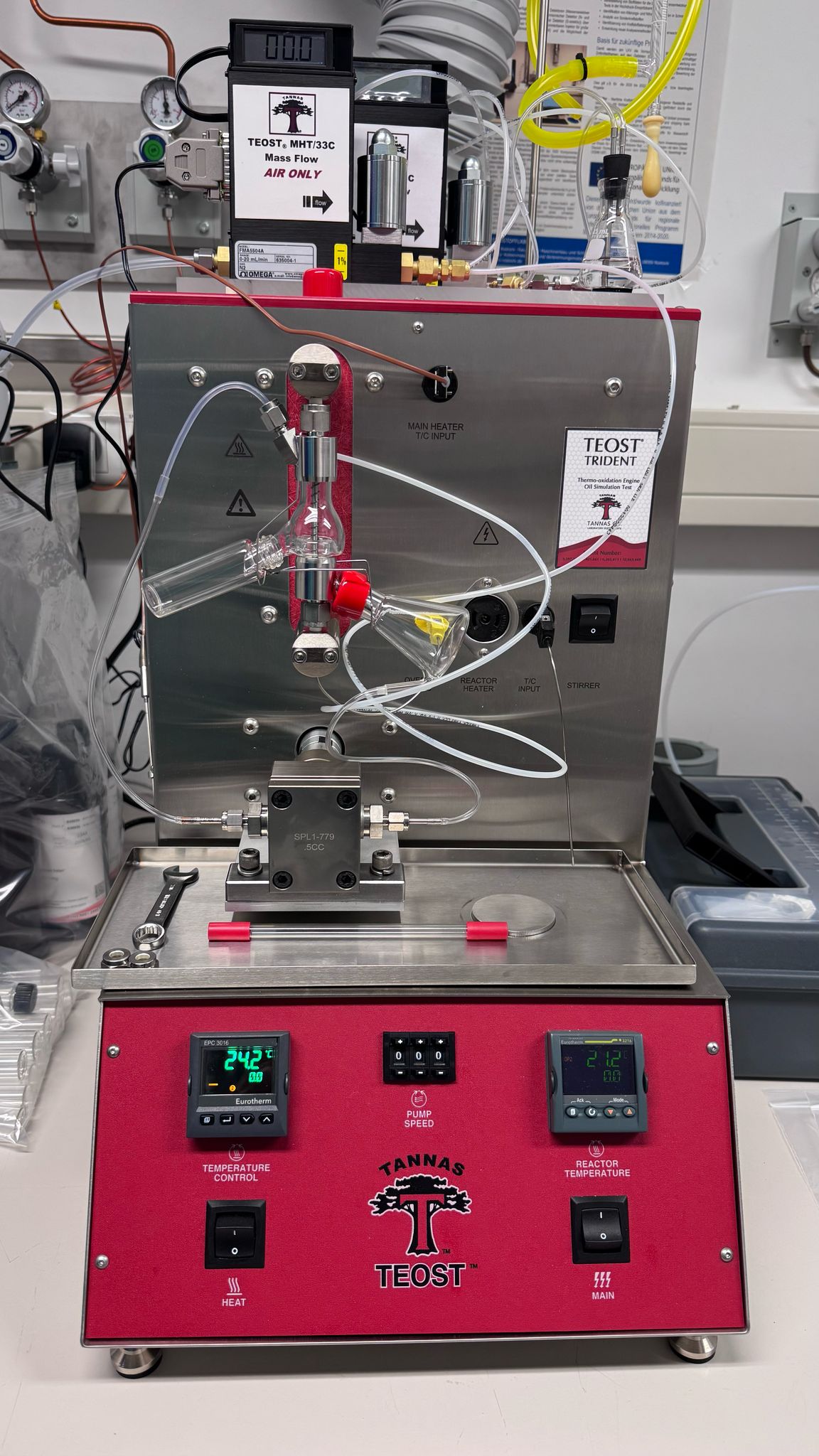
The Thermo-oxidation Engine Oil Simulation Test (TEOST® test) simulates the oxidation and deposit tendency of engine oils.
The three current TEOST® test procedures are carried out under temperatures and environmental conditions that are relevant for combustion engines in order to simulate the oxidation and deposit tendency of engine oils and are part of engine oil specifications.
Unlike oxidation tests, which are based on visual colour perceptions and variable human assessments, the TEOST® tests provide results based on a gravimetric analysis of the mass of deposits formed on the depositor rod and the mass of particles otherwise generated in the circulating oil. For this purpose, oil samples treated with a catalyst are pumped over a heated steel test rod on which deposits form. The weight of the test rod after the test is subtracted from its initial weight before the test and added to the weight of the particles collected during filtration of the remaining oil.
The TEOST MHT® (according to ASTM D7097) simulates the formation of deposits in the piston belt area, which occurs through a ‘thin film’ oxidation process. The TEOST MHT® replicates this process by exposing a thin film of lubricant to the passing gases, similar to the oxidation that occurs in an engine when large areas of oil are exposed to the passing gases. The test temperature is kept constant at 285°C, with a test duration of 24 hours to simulate the ring band temperatures. The deposit formation in the TEOST MHT® test could also correlate with the deposit tendency of oils that enter the exhaust gas stream.
The original turbocharger deposit test (TEOST® 33C ASTM D 6335) was developed to test engine oils for their tendency to form coking deposits in the high-temperature areas of the turbocharger.
The TEOST Turbo® ASTM D8447 test method was developed to simulate turbocharger deposits that are more oxidative in nature and occur at lower temperatures.
At the LKV, this test device is used as part of the ‘AmmoniaMot2’ project to test whether engine lubricating oils that have come into contact with NH3-containing combustion and exhaust gases show an increased tendency to form deposits.